


Networking technologies have continued to advance over the years. New technologies continue to replace previous de facto standards and enable previously unforeseen capabilities. What we take for granted today may have seemed impossible ten or fifteen years ago.
Ethernet technologies are a perfect example of this. When the IEEE 802 standard was initially ratified it was limited to 10 Million bits per second (Mbps). Today we now have available multi-Gigabit Ethernet technologies to allow the transmission of large amounts of data. This new age of Ethernet has enabled services, such as video on demand and streaming video, that would have been impossible 20 years ago.
This new multi-Gigabit capability has revealed limitations in the media used for transmission. In most cases the only media that can support this rate of transmission over larger distances, such as connecting network distribution points, is fiber optic cabling. Fiber optic cable consists of actual glass fibers, not much larger than a human hair, to carry the data transmission signals created by modulating photons or light from a source such as LEDs and lasers. The signaling travels down this glass strand by bouncing, or refracting the light, off the walls of the fiber core and its cladding. The following diagram shows a cut-away side view of a fiber optic cable and illustrates how the photons traverse it and the main differences between multi-mode and single mode types of cable.
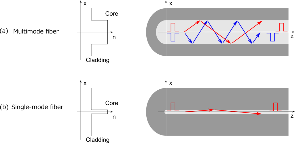
Note that in the illustration above we are transmitting using multiple transmission paths on the multimode cable and a single transmission path on the single mode cable.
Although the speed of light in a vacuum in 186,282 miles per second the speed through a silicon glass media is approximately 31% slower. This is still a significantly fast transmission rate and can support extremely high data rates. Although it is generally true that fiber optic cabling is immune to Radio Frequency (RF) noise that can cause a failure in the communication and is capable of longer distances than conventional twisted pair wire cabling, there are limitations in how it can be successfully applied.
The limitation of how far data can be transmitted in a fiber optic cable is a function of the rate of transmission and the type of fiber optic cable that is used. Modal Bandwidth refers to the maximum signaling rate for a given distance. It can also be expressed as the maximum distance for a given signaling rate. These parameters influence the distance you can expect to transmit on an optical fiber given the known transmission rate and type of cable.
There are a several categories of fiber optic cabling. It is important to understand what type of cable is being installed. As previously mentioned, the two main distinguishing types are multimode and single mode cable. Most interior cabling that has been installed since the initial introduction of fiber optic cabling is multimode. Single mode has historically been used for long-haul or connecting sites that are separated by large geographical distances.
It is important to understand that not all multimode fiber optic cabling is the same. They can vary significantly and have an impact on the network design. In the table below you can see the various types of optic cabling and their Modal Bandwidth ratings:
| Category | Minimum modal bandwidth 850 / 953 / 1300 nm | Fast Ethernet 100BASE-FX | 1 Gb (1000 Mb) Ethernet 1000BASE-SX | 1 Gb (1000 Mb) Ethernet 1000BASE-LX | 10 Gb Ethernet 10GBASE-SR | 40 Gb Ethernet
40GBASE-SWDM4 | 40 Gb Ethernet 40GBASE-SR4 | 100 Gb Ethernet 100GBASE-SR10 |
| FDDI (62.5/125) | 160 / – / 500 MHz·km | 2000 m | 220 m | 550 m (mode-conditioning patch cord required) | 26 m | Not Supported | Not supported | Not supported |
| OM1 (62.5/125) | 200 / – / 500 MHz·km | 275 m | 33 m | Not Supported | Not supported | Not supported | ||
| OM2 (50/125) | 500 / – / 500 MHz·km | 550 m | 82 m | Not Supported | Not supported | Not supported | ||
| OM3 (50/125) *Laser Optimized* | 1500 / – / 500 MHz·km | 550 m (no mode-conditioning patch cord should be used) | 300 m |
240m Duplex LC |
100 m (330 m QSFP+ eSR4) | 100 m | ||
| OM4 (50/125) *Laser Optimized* | 3500 / – / 500 MHz·km | 400 m |
350m Duplex LC |
150 m (550 m QSFP+ eSR4) | 150 m | |||
| OM5 (50/125) “Wideband multi-mode” for short-wave WDM | 3500 / 1850 / 500 MHz·km |
The selection of the correct cable will be imperative to ensure that the design distance is achieved. For example, if we intend to connect two locations that are 500 feet (152.4 meters) apart at 10 Gbps we will need to ensure that we are using at least OM3 rated multimode cable with a 50 um (micrometer) core diameter.
Have any questions about fiber optics? Feel free to contact us at any time!
This publication contains general information only and Sikich is not, by means of this publication, rendering accounting, business, financial, investment, legal, tax, or any other professional advice or services. This publication is not a substitute for such professional advice or services, nor should you use it as a basis for any decision, action or omission that may affect you or your business. Before making any decision, taking any action or omitting an action that may affect you or your business, you should consult a qualified professional advisor. In addition, this publication may contain certain content generated by an artificial intelligence (AI) language model. You acknowledge that Sikich shall not be responsible for any loss sustained by you or any person who relies on this publication.